Using terminal I/O in PIC32 programs
Intro
Micro-controller boards, such as Arduino or Digilent ChipKit Max32, do not have any connectors for displays or user keyboards (or, at least, standard connectors). Nevertheless, in many circumstances, we require reading values displayed on a monitor or entering data via a keyboard. Particularly in the debug phase of the software, it is handy to have some means for the program to output the value of some variables, for instance, or information about what is it doing. A possible alternative is, of course, to use the debugging facilities of the MPLab IDE (see this post). But the terminal input and output may be also a required feature for the program, so there are reasons to consider it.
In this post, we will see how to generate terminal output from a PIC32 micro-controller; in other words, how to use the printf() function in a micro-controller program.
Terminal Input/Ouput in micro-controller boards
Most micro-controller include in their internal peripheral devices one or more UART (Universal Asynchronous Receiver/Transmitter) controllers, enabling serial communication. Many current boards connect this UART to the USB controller. In this way, the micro-controller can send and receive data via the USB cable. By connecting the board to a PC using USB, it is possible to use the PC screen and keyboard to display data to the user and read the user keystrokes.
On the PC side, we require a program that collects what is received by the USB cable and display it on the screen, and reads the keyboard and sends what is typed on the keyboard to the micro-controller board. This kind of program is called a terminal emulator, because it emulates the operation of a computer terminal. In our case, we will use PuTTY, a free, open source terminal emulator for Windows, Unix and MacOS. You can download it from PuTTY’s site; for most Linux distros, PuTTY is available as a package.
Previous requirements
Work described here supposes that you have installed Microchip development tool chain (IDE and compiler) (see this post) and that you have a development board with a Microchip PIC32 micro-controller (in this case, Digilent ChipKit Max32)
Terminal I/O example
The project UART_Demo_SAI contains and example of program for the ChipKit Max32 board using terminal input and output. The program displays a welcome message and then reads the keys pressed by the user to turn the led on and off: + to turn the led on, - to turn it off and x to toggle the led state.
This program uses a module for handling serial communication. This module includes the uart.c and uart.h files, distributed in the project zip file, in the Common/UART folder. The module defines four functions:
UartInit: intializes and configures the UART.UartClose: closes the UART (currently, does nothing…)PutChar: sends one char via the UARTGetChar: receives one char via the UART
Terminal configuration
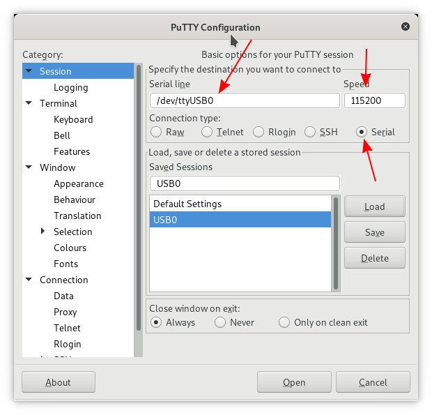
The UART_Demo_SAI program configures the serial line (USB is a serial line) for a 115200 baudrate. Selecting “Session” in the “Category” menu, on the left hand side of the PuTTY window, the configuration should set a serial connection on the USB port with a baud rate of 115200.
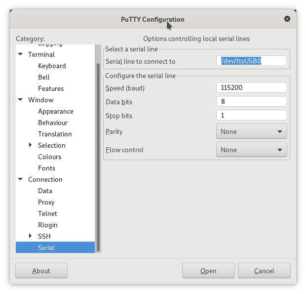
Selecting “Serial” under “Connection” on the Category menu will provide more details on the serial line configuration.
For Linux users, the USB appears as /dev/ttyUSB0 or similar (/dev/ttyUSB1, …). For Windows users, an FTDI device appears in one of the COM lines 1
You should now be able to run the program in the ChipKit Max32, see the welcome message in PuTTY terminal window and control the led state with the keys.
-
FTDI is the manufacturer of the chip that converts from serial coming out of PIC32 to USB. The PIC32 contains an UART, that enables serial communications. The FTDI chip converts the PIC32 serial line communication to the USB protocol, enabling communication with the PC. ↩
Comments
Your comments are welcome. Feel free to leave here your remarks or your opinion!