The config_bits.h file and oscillator configuration
- Intro
- What are “configuration bits”?
- Example of configuration bits programming
- Configuration bits and micro-controller clock
Intro
When developing projects for the PIC32 micro-controller (and particularly when you have friendly lecturers), you may use a .h file containing the code for setting the configuration bits. Often, this file is just included without much regard for its contents. Along with this, comes the assumption that this file was correctly generated and that it is adequate to our purposes. This is not always true, so care must be taken.
Besides, engineers (and this is a text written to Engineering students…) are supposed to be proficient with the machines they use. If you are (or intend to be) an Electronics or Computer Engineer, this means, among other things, that if you use some code, you should know what does it do.
In this post, we will have a look at the contents of the config_bits.h file that is distributed in our department in some of the courses introducing the PIC32 and have a look at what is the meaning of the settings in this file, particularly in what concerns the functioning of the micro-controller clock.
What are “configuration bits”?
The configuration bits are part of several non-volatile registers in the SFR (Special Function Regiter) area that control the device behaviour in regard to several features, such as oscillator configuration, defining the device clock, watchdog timer, and others. Configuration bits (or configuration words) are described in section 32 of the PIC32 Family Reference Manual.
Example of configuration bits programming
The file config_bits.h is an example of a configuration file. It contains a set of #pragma instructions that the XC32 compiler uses to program the required registers. This file should be the first #include directive in the code and should be included only once (if you include it more than once, the #pragma once directive in the start of the file will prevent multiple inclusions).
Configuration bits and micro-controller clock
In this section will will have a look at the contents of the config_bits.h file and how they define how the micro-controller clock works.
PIC32 Clock circuit
Before looking at the code, let us have a look at the hardware that is programmed by the code. The following figure is extracted from the PIC32MX5XX/6XX/7XX Familiy Data Sheet:
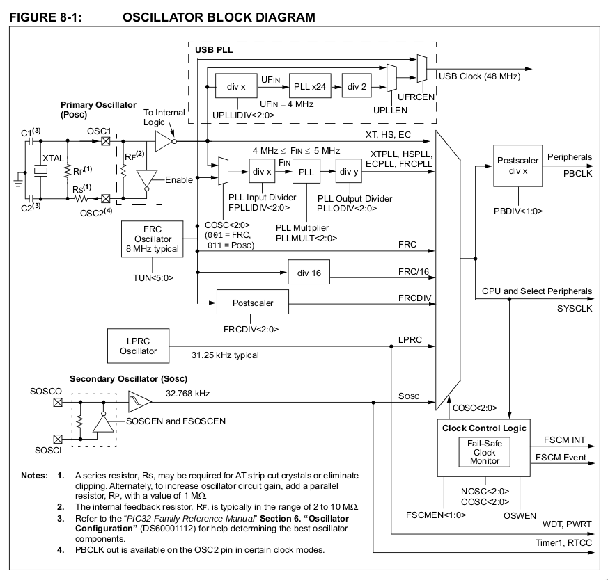
On the left side we have the available sources for the clock signal:
- Primary Oscillator (POsc);
- FRC (Fast RC) Oscillator;
- LPRC (Low Power RC) Oscillator; and
- Secondary Oscillator (SOsc).
On the right side, we find the several clock signals driving the micro-controller circuits. In this example, we are interested in the System Clock (SYSCLK) and Peripheral Bus Clock (PBCLK). In between, lays all the circuitry required to generate a clock signal from the clock sources. These include switches (to select which of the available signals will be used), PLLs (Phase Lock Loops, to multiply the frequency) and frequency dividers. Along with the hardware, the figure presents the configuration bits (e.g., COSC<2:0>, PLLMULT<2:0>, …) that control the hardware configuration.
In short, the circuit works as follows:
- COSC<2:0> (Current Oscillator Selection bits) control the main switch and define the signal to be used as the clock for the micro-controller;
- depending on this selection, the circuits in the selected clock path need to be configured;
- for PBCLK, the Postscaler will define the relation between SYSCLK and PBCLK.
Besides this, the programmer needs to take care of some details, as will be shown in the following.
Reading the config_bits.h file
The Configuration Words relevant for programming the micro-controller clock are DEVCFG1 and DEVCFG2. Starting with DEVCFG1, the example file provided contains the following:
// DEVCFG1
#pragma config FNOSC = PRIPLL           // Oscillator Selection Bits (Primary Osc w/PLL (XT+,HS+,EC+PLL))
#pragma config FSOSCEN = ON             // Secondary Oscillator Enable (Enabled)
#pragma config IESO = ON                // Internal/External Switch Over (Enabled)
#pragma config POSCMOD = HS             // Primary Oscillator Configuration (HS osc mode)
#pragma config OSCIOFNC = OFF           // CLKO Output Signal Active on the OSCO Pin (Disabled)
#pragma config FPBDIV = DIV_2           // Peripheral Clock Divisor (Pb_Clk is Sys_Clk/2)
#pragma config FCKSM = CSDCMD           // Clock Switching and Monitor Selection (Clock Switch Disable, FSCM Disabled)
#pragma config WDTPS = PS1048576        // Watchdog Timer Postscaler (1:1048576)
#pragma config FWDTEN = OFF             // Watchdog Timer Enable (WDT Disabled (SWDTEN Bit Controls))
- The first line sets the oscillator selection bits to the option “Primary Oscillator with PLL”. This sets the source oscillator to be the Primary Oscillator and that the line choosen is the one that goes through the PLL (frequency multiplier). A direct consequence of this choice is that the PLL and the frequency dividers will have to be configured.
- The second and third line enable the Secondary Oscillator and enable the possiblity of switching between internal and external oscillator.
- The fourth line define that the Primary Oscillator will be running in HS mode.
Comments
Your comments are welcome. Feel free to leave here your remarks or your opinion!