Debouncer
Description
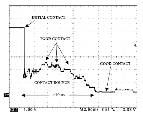
When you push a button, as instantaneous as it might seem to you, the button contacts don't actually stay immediately connected, they bounce a little and then rest to a stop finally making a good electrical contact. The same thing happens when contact is broken, the electrical connection is not cut instantly.

Bouncing may occur from a few µs up to 20ms, sometimes more, even in the same button times vary a lot and tend to degrade with usage. At high frequencies like the ones used in FPGA boards in the range of MHz, that means a lot of clock periods of uncertainty.
During that poor contact time it's a digital twilight zone, the signal level raises and lowers many times and often stays between the logic level thresholds, it's not logic 1 and not logic 0 but your logic circuit inputs a bunch of random 1's and 0's during that time.
Many FPGA boards don't have debouncing circuits to clean up the signals from the push buttons, slide switches or DIP switches, but it's necessary to do so in your code.
Oscillation may also occur from other sources, for example the keyboard or mouse PS/2 lines or any other outside of the board source you are connecting from, those may also need signal filtering, the signal itself may already be a little corrupted with noise, the wires may pick up electromagnetic interference, if the source system has poor step response it may have long settling times(compared with your clock frequency).
If you're using buttons/switches or external signal sources, you should use a debouncer.
How does it work?
It's just a simple clock cycle counter that resets when the input changes, if the input stays unchanged until the counter finishes, it's considered stable and outputs the correct logic level. That amount of clock cycles is defined in a generic parameter in the VHDL entity instantiation.
Example:
For button/switch debouncing I usually use 5ms delay, remember that delay is measured after all the initial bouncing, it´s a safeguard band that you think no more bouncing is going to happen, but sometimes it does, bounces and stabilizes and bounces some more, make it always a few ms delay for buttons/switches.
For the case in the picture above, from the initial contact until the signal is stable in the debouncer output, it would measure about 15ms, 10ms of contact bounce plus 5ms delay, you can't notice a 15ms delay, it appears instant, but in the end your signal is clean.
Make your calculations!
Time delay(in µs) x Clock frequency(in MHz) = Counter limit
5ms at 50MHz becomes...
5000 x 50 = 250000
So 250000 is your generic parameter for 5ms delay at 50MHz board clock.
Another example:
For signal filtering 5ms is definitely too much, in the PS/2 controller I use two debouncing modules, one for the data and another for the keyboard generated clock, the parameter is defined at 16 for the delay, that is 16 clock cycles after the last detected oscillation I consider the signal stable, at 50MHz that's only 0.32µs but I haven't found a keyboard that gives me trouble with that setting.

